500W Royer induction heater
Project description
Often I used to run onto people on 4hv asking for a simple induction heater design they could play with at home without big money investments. Since I’ve acquired lots of experience with Royer oscillators for wireless power applications, I recommended a modified version of “Mazzili flyback driver” could be used for a quite powerful induction heater. However, the idea didn’t seem to catch on, so I decided to try and build my own version.
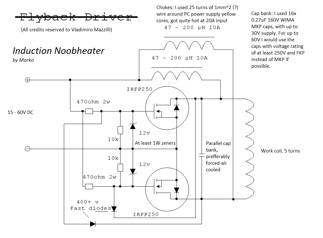
The original Mazzili flyback driver schematic was modified to work for an induction heater
The few changes I made compared to the flyback driver were:
- Of course, replacing the flyback with a suitable 5-turn work coil
- Two inductors were used to avoid tapping the work coil, a standard procedure for me now
- I used IRFP150 MOSFETs, instead of IRFP250’s mainly because they were at hand
- Increasing the tank capacitance a lot, with lots of parallel capacitors for increased current carrying capacity: I used 16x 0.27uF, 1ooV WIMA MKP capacitors if I remember correctly. This continues to work well despite the tank currents approaching 150A!
- I used water cooling for both the work coil and the mosfets, removing need for bulky and costly heatsinks. I heavily recommend water cooling for any hobbyist power electronics now! It was somewhat difficult to solder the copper plates to the pipe, but I made it using a stove and generous amounts of solder. This circuit makes great use of water cooling because no electrical insulation is needed for MOSFETs, as drains are already electrically connected to the work coil!

Prototype version

The cooling plates are soldered so that the pipe passes right underneath the MOSFET die

Capacitors are generously spaced to allow good convection cooling

Inductors are wound by hand on two powdered iron cores from PC power supplies
The power output of the circuit surprised even me, being able to melt small steel, brass and aluminum parts with ease. The power throughput seemed to be mainly limited by the power supply, which had to provide less than 30V (due to MOSFET rating) at a whole lot of current.
A video of melting some coins
The circuit was later replicated successfully by lots of other hobbyists as well!
Links and references
[1] 4hv thread http://4hv.org/e107_plugins/forum/forum_viewtopic.php?122354.120
[2] An example replication http://kaizerpowerelectronics.dk/general-electronics/royer-induction-heater/

Hi, i’m doing this project for the fifth year of my school..Do i have to connect the royer to a trasformer or i can connect it to a Dc power supply??? Sorry for my bad english…
Hi.. i’m doing this project for the fifth year of my school. I have question: Do i need to put a trasformer back to the royer (the schematic that have been posted by you). Thank you and sorry for my bad english. xD
Hi,
which is the diameter the work coil and tube?
Hi. great project but i think you have to had the diameter of the coil and the pipe. I have a question, why do you use direct current?
hello ,what should i do if i want to use 220 volt power supply for this circuit ?
As you are switching the work coil you are also pulling one of the V+ inductors to ground. Isn’t that a waste ?
I should say isn’t that a waste of I being pulled through that V+ inductor ? Please explain as I want to construct this. I will be using T 130-26 pft’s
Hi, I’m Thapelo
I’m doing my project that is dealing with induction heating, I used 2.2uF cap for resonance but i cant detect any magnetic field. i can measure current of about 10A, but if i put conducting wires on my work coil, it does not heat up.
Which material do you recommend for work coil?
Muy bueno el dispositivo. Sencillo y eficaz. Felicitaciones.
Could I buy one of these from you, premade?
How kHz? Measured?
possible on IRF 3205 or not?
hii sir,
I’m working on this project on large power approximately 10kva for a melting furnace
sir its schematic is able to do that if yes, what changes will have done..kindly reply
wooooow,it’s wonderfull,….smallthing from exacta sciences…..
This is a brilliant circuit. It uses two boost converters in an ingenious manner such that they act as current source to match the parallel resonant circuit during half a cycle. Also the heavy capacitor acts as snubber to the two switched inductors in turn and thus the harmonics on the supply are reduced to a minimum. The energy pumped into the parallel LC resonant circuit depends on how much energy each boost converter on either side of the LC circuit is made to hold!
Any hard switched Mosfet is a voltage source which is not suitable to match a parallel LC circuits but this one charges the inductor with a magnetic charge when the Mosfet is on and when it is off the charged inductor becomes a current source perfectly matching the Parallel LC circuit while the other Mosfet is on to complete the circuit. Then the function is repeated for the other half cycle using the other side,
One of the most ingenious circuits I met.
Now I am working on a similar one to match a series LC circuit, but it will not be as neat as this one.
My congratulations.
Приветички!
Сматрите как я обоссую рулетку http://rbot.imob.su/
Захадити ставь лайки. Ни веди сибя как падлын сын.
Приветички!
Аднажды мы с маей телкой играли в казине и она покакала на рулетку и я выграл. Сматри видио: http://rbot.imob.su/
Захадити ставь лайки.
Удачички!!!
Dear sir
I want to communicate with you about induction heaters.
Well Sir,
Regarding induction heaters there are a few clues one needs to communicate but one may stick to this particular circuit. If the size of the induction coil is approximately the same size as the work-piece then the transfer of energy is better.
One must be careful how much power rating the zener diodes take as increasing the supply voltage beyond some value may burn them out.
In this circuit the energy does not go straight from the power supply to the induction resonant coil but first it is accumulated in the two main high value inductors acting as drain loads to the Mosfets. and then the energy accumulated is transferred to the induction parallel combination of the induction LC arraignment.
Assume one Mosfet is on due to the 470 ohm resistance pulling the gate up. This will cause current/energy to pass into the high inductor at its drain. The amount of current that is permitted to rise depends on the duration, the value of the inductance and the supply voltage. ( during this time the MOSFET is acting as a voltage source with low output impedance and the inductor must not be allowed to saturate! Then this MOSFET is switched off , but the current in it cannot stop flowing and it tries to cause a high positive voltage spike at the drain but it will find the capacitor connected to it and as the other MOSFET now holds the other end of the capacitor low short circuited to low voltage, the positive spike does not occur but the capacitor acts as a heavy snubber to the voltage spike while the current in the heavy inductor will now act as if it is coming from a current source. This will raise the voltage of the capacitor and it keeps going up till most of the energy in the heavy inductor is used up to charge the heavy capacitor, and the nature at which it does it is almost as a half sine wave due to the LC induction circuit. One the voltage rises to maximum, it will find the induction coil across it which will cause the heavy capacitor to discharge with enormous current and the rate of change of the current will create a magnetic field which as it changes it induces the secondary current in the work-piece.
Note as the voltage across the capacitor decreases it will find the gate diode hence switching of the Mosfet that was on and whose drain inductor had been charged and now becomes its turn to charge” the other side of the capacitor. What appears to be two positive half wave positive going waveforms at the drain will be passed over to the secondary side, the work piece as a very good sine wave.
There is nothing much else to say about this circuit as if one wants power all one needs to do it to chose the right components with the right ratings.
I made one of these for my students and matched the system to a loop antenna. It works fine and for the students to see such power being transferred to a receiving loop antenna , they are quite thrilled.
The circuit is very versatile and matching the coil will permit this circuit to be used as an induction heater and also to feed a loop antenna. Note that for teaching purposes, I stick to frequencies around 200khertz., they seem to heat and radiate as required.
What I like about this circuit is the clever manner in which what looks like two half sinewaves at the drain are summed up neatly to produce a sine wave all this with SWITCHING MOSFETS.
obviously it is all thanks to the heavy capacitor acting as a good snubber to those would be spikes at the drains had the capacitor been absent.
Congratulations to the designer of this nice little circuit. Hope this helps.